

SPI
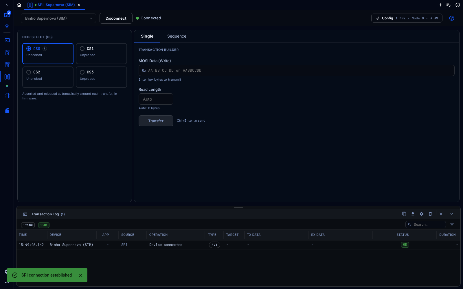
SPI tool connected to a simulated Supernova
The SPI tool runs SPI transfers, with the adapter as the controller.
Connect
Section titled “Connect”Connect the adapter as described in Connect a Tool. Config at the top right opens the settings for the SPI bus.
Configure
Section titled “Configure”In Config, set the bus frequency, the SPI mode (0 to 3), the bit order, the chip-select polarity and the target voltage (VTARG), then click Apply. The target voltage is shared with I2C, UART and GPIO on the same adapter.
Chip Select
Section titled “Chip Select”Choose CS0, CS1, CS2 or CS3. The adapter asserts the chip select before each transfer and releases it afterwards.
Transfer
Section titled “Transfer”In the Single tab, enter the bytes to send in MOSI Data (Write) and, if more bytes are expected back than are sent, a Read Length. Click Transfer, or press Ctrl+Enter. The bytes received on MISO appear in the Transaction Log. The Sequence tab builds multi-step sequences.