
GPIO
Selecting  in the Navigation Menu opens the GPIO (General-Purpose Input/Output) command panel.
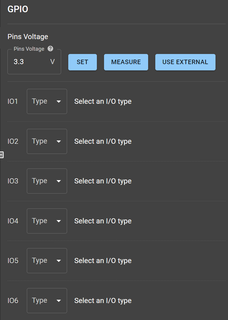
Initial GPIO command panel for Supernova.
For GPIO, a pin can be set to one of six configurations: Analog Input (AIN), Analog Output (AOUT), Pulse Width Modulation (PWM), Digital Input (DIN), Digital Output (DOUT) and Interrupt. The table shows what each Nova IO pin (N), Supernova IO pin (SN) and Pulsar IO pin (P) supports.
| Pin | AIN | AOUT | PWM | DIN | DOUT | Interrupt |
|---|---|---|---|---|---|---|
| IO0 | N | - | N | N | N | - |
| IO1 | N | N | - | N - SN - P | N - SN - P | SN - P |
| IO2 | N | - | N | N - SN - P | N - SN - P | SN - P |
| IO3 | N | - | N | N - SN - P | N - SN - P | SN* - P |
| IO4 | N | - | N | N - SN - P | N - SN - P | SN - P |
| IO5 | - | - | - | SN - P | SN - P | SN - P |
| IO6 | - | - | - | SN - P | SN - P | SN - P |
*Supernova Rev. B does not support GPIO interruptions on pin 3.
Notes:
- Analog Input (AIN): When a pin is set to AIN, a READ button appears. Pressing it measures the pin voltage and shows the result in the Transaction Log View.
- Digital Input (DIN): Pins configured as DIN behave similarly to AIN. The result is binary: Low or High.
- Analog and Digital Output (AOUT/DOUT): These pins show a WRITE button and a textbox. For AOUT, enter a voltage from 0.0 V to 3.3 V. For DOUT, the textbox is a dropdown with Low and High.
- Pulse Width Modulation (PWM): PWM pins have a duty cycle and a frequency. The frequency is 750 Hz to 80 kHz, and the duty cycle is 0% to 100% in whole numbers. IO0 and IO2 share a frequency setting, as do IO3 and IO4: changing one changes the other.
Example
Section titled “Example”An example with the simulator:
- An analog READ on IO0 returns 0.0 V.
- An analog WRITE on IO1 sets 1.0 V.
- A PWM WRITE on IO2 sets 1950 Hz at a 75% duty cycle.
- A digital READ on IO3 returns High.
- A digital WRITE on IO4 sets Low.
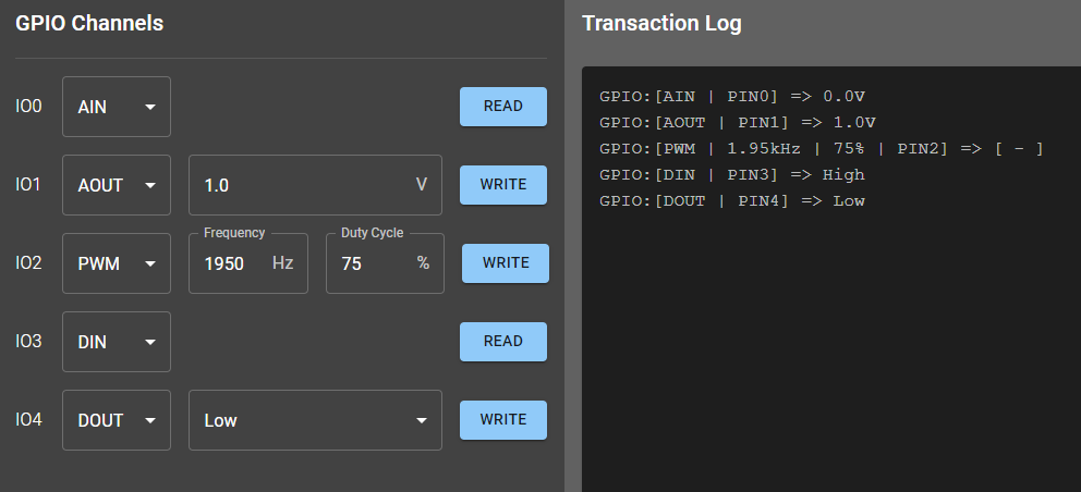
GPIO example for Nova.
For all protocols, READ and WRITE results appear in the Transaction Log View.