

Binho Pulsar: Setup
Connect a Binho Pulsar to the computer and to the circuit, and check that it works.
Connection to the Host PC
Section titled “Connection to the Host PC”Connect the Pulsar’s rear USB Type-C port to the computer with the supplied USB Type-C to Type-A cable, or with the Type-A to Type-C adapter for a Type-C port. The Pulsar is powered from USB; no external supply is needed. It is a USB 2.0 High Speed device (480 Mbps).
The Pulsar is a USB HID device, so Windows and macOS need no driver. On Linux, allow the current user to access it once, as described in Solving USB Connection Issues on Linux.
The Pulsar also appears as a USB serial port (a COM port on Windows, /dev/ttyACM* on Linux, /dev/cu.usbmodem* on macOS). It carries the UART, or RS-485 or CAN-FD when its mode is switched. See Virtual COM Port Modes.
Check that the computer sees it
Section titled “Check that the computer sees it”With PyCosmicSDK installed (pip install pycosmicsdk):
import pycosmicsdk
for d in pycosmicsdk.list_devices():    print(d.model, d.serial_number, d.fw_version)
Nothing is sent to the adapter: the model, serial number and firmware version come from its USB descriptor. If the list is empty, check the cable and, on Linux, the permissions above. If the firmware version reads bootloader or 3.x.x, see Updating Firmware.
Connection to the Test Circuit
Section titled “Connection to the Test Circuit”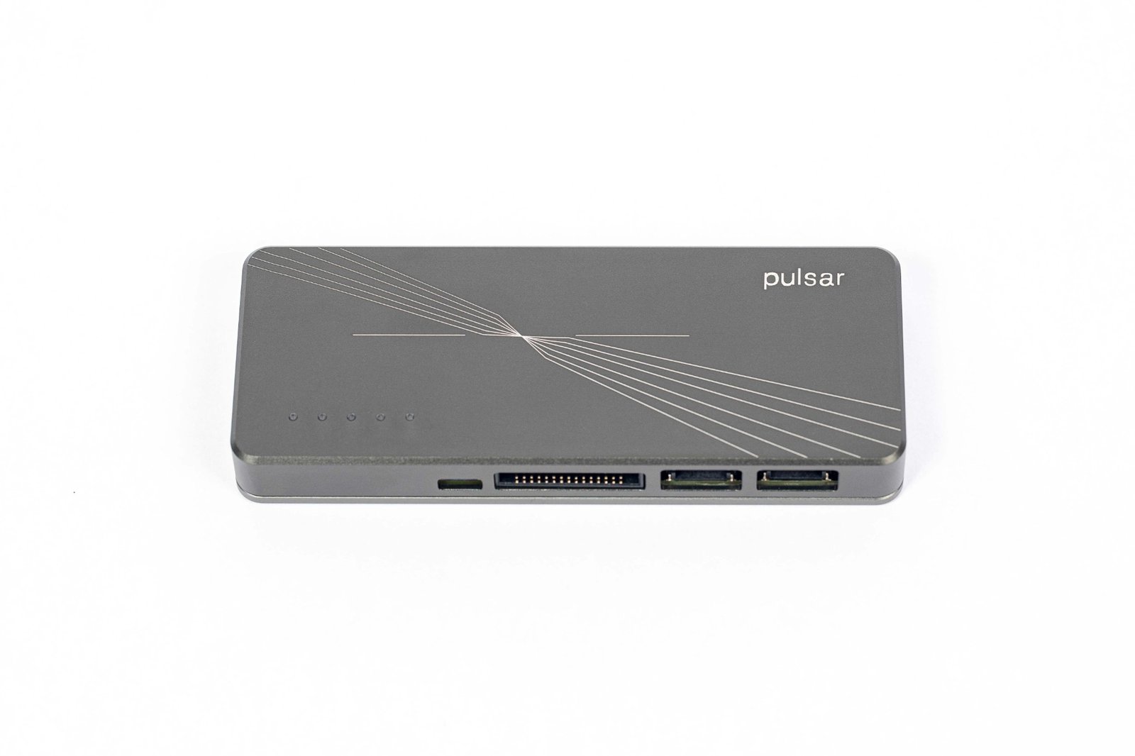
The four front ports of the Pulsar.
The front of the Pulsar has four ports for the device under test. Use the cable kit that matches the port:
| Port | Use it for | Cables in the box |
|---|---|---|
| Multifunction Port | I2C (bus B), SPI, UART, GPIO | 30-conductor ribbon cable and a breakout board to 2.54 mm headers |
| Dedicated I2C Port | I2C (bus A), Qwiic devices | Qwiic to Qwiic cable, and Qwiic cables with male or female headers |
| RS-485 Port | RS-485 bus | 4-pin JST PH cables with male or female headers (shared with the CAN-FD port) |
| CAN-FD Port | CAN-FD or CAN bus | Same 4-pin JST PH cables |
For every pin, see the Pinout Guide.
Target Voltage (VTARG)
Section titled “Target Voltage (VTARG)”The Multifunction Port and the Dedicated I2C Port share one target voltage rail, VTARG, between 1.2 V and 3.3 V.
- The board has no supply: set the voltage it expects from Mission Control 3 or the SDK before enabling a bus. The Pulsar powers the board through VTARG, up to 200 mA.
- The board has its own supply: do not set a voltage. Select external voltage (
use_external_voltage()in the SDK) and connect the board’s logic supply to VTARG.
The RS-485 and CAN-FD ports have a fixed +5 V output that is always on.
Always connect ground between the Pulsar and the device under test.
First Steps
Section titled “First Steps”- Without code: open Mission Control 3, as a desktop app or in a Chromium browser at mc3.binho.io, and select the Pulsar under Connected Devices.
- From Python:
pip install pycosmicsdk, then follow Getting started with PyCosmicSDK. The Pulsar user guide has I2C, SPI and CAN-FD examples. - From C or C++: see the CosmicSDK documentation.
- Check the firmware: the examples on these pages assume firmware 4.6.x. See Updating Firmware.